 +86-13989680588
 graylin@hongjiavalve.com
Submit feedback
What Is a Threaded Stop Valve and How Does It Work
Author: Hongjia
Date: Jun 16, 2026
Fluid moving through pipes rarely behaves in a perfectly stable way. Water demand rises, then drops. Cleaning work interrupts flow. Small sections of a system need isolation without shutting everything down. A Threaded Stop Valve often appears in those points where control needs to stay simple and direct.
In real installation work, technicians tend to favor components that do not require complex tools or permanent joining methods. Threaded connection fits that situation. Pipe ends can be joined by rotation, which makes placement easier in tight corners or short pipe gaps. A valve placed in such a section can be removed later without cutting the pipeline.
Daily examples are easy to notice. A kitchen water line may need temporary shut-off during faucet replacement. A storage tank connection may require isolation during cleaning. In those moments, a Threaded Stop Valve becomes a practical control point rather than a complex system component.
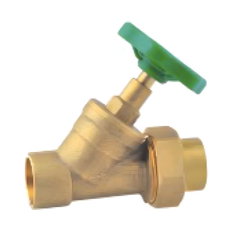
A Threaded Stop Valve is built around a compact body designed to fit between two pipe sections without adding much length to the system. The structure usually feels simple from outside, yet each internal part plays a specific role.
Main parts often include:
- outer housing that holds pressure
- threaded inlet and outlet for pipe connection
- internal moving element that adjusts passage size
- sealing ring surfaces for tight closure
Inside the valve body, a movable component travels along a guided path. That movement changes the opening inside the pipe. When lifted or lowered, the space for fluid passage changes gradually rather than suddenly.
Threaded ends allow connection by rotation. Once installed, the valve becomes part of the pipeline line, while still allowing internal adjustment from the external handle.
Sealing materials sit between moving and fixed parts. Their role is simple in concept: reduce leakage when the internal passage is closed or partially restricted.
How Threaded Stop Valve Controls Fluid Flow
Control inside a Threaded Stop Valve relies on vertical or linear movement of the internal element. Turning the handle shifts that element up or down, changing how much space remains for fluid to pass.
Three common positions appear during everyday use:
- open position allowing free movement
- partially open position restricting flow
- closed position blocking passage completely
In an open position, internal channels align with the pipe direction. Fluid passes with little interruption, similar to a straight pipe section.
During partial adjustment, flow path becomes narrower. Water speed changes, pressure distribution becomes uneven, and flow noise may appear in some systems.
Closing the valve brings internal sealing surfaces into contact. Once contact is complete, flow stops at that section of the pipeline.
This type of control feels mechanical and predictable. Each rotation of the handle directly changes internal spacing rather than relying on external sensors or automatic regulation.
What Happens Inside Threaded Stop Valve During Operation
Inside the valve body, fluid behavior changes depending on internal position. When the valve is fully open, pressure moves through without much resistance. Internal walls guide flow in a straight direction.
During partial opening, flow begins to interact with narrowing space. Speed increases in some zones while slowing in others. That uneven movement creates mild turbulence inside the valve body.
Closing movement introduces direct contact between sealing surfaces. At that point, fluid is blocked at a defined boundary. The system upstream still holds pressure while downstream becomes isolated.
A simple view of internal states:
| Valve Position | Internal Condition | Practical Effect |
|---|---|---|
| Fully Open | Straight passage | Normal flow through pipe |
| Partially Open | Narrowed channel | Reduced and uneven flow |
| Fully Closed | Seal contact | Flow isolation |
Repeated daily use creates wear patterns on sealing surfaces. Smooth movement depends on how evenly those surfaces interact over time.
Why Threaded Connection Matters In Installation
Threaded connection is widely used because it matches real installation conditions. Pipes are often placed in corners, narrow cabinets, or behind walls where welding or permanent bonding is difficult.
Installation usually follows a simple sequence:
- aligning valve with pipe ends
- rotating threads into position
- tightening until stable fit is reached
This method allows installation in areas where space does not allow complex tools. It also supports removal when maintenance is needed.
In household environments, threaded connection makes it easier to replace parts without rebuilding the whole pipe line. In small workshops or auxiliary systems, it supports repeated adjustments during system changes.
Another practical point is alignment flexibility. Slight adjustments during tightening help match pipe direction without forcing rigid positioning.
Where Threaded Stop Valve Is Commonly Used
A Threaded Stop Valve appears in many everyday fluid systems where simple isolation or adjustment is needed.
Typical environments include:
- household water supply lines
- small irrigation systems
- maintenance sections in plumbing layouts
- auxiliary branches in fluid networks
In a home setting, it may be placed under sinks or near water tanks, where occasional shut-off is required. During repair work, closing the valve isolates a section without affecting the rest of the system.
In small mechanical setups, it often acts as a control point between main and branch lines. Instead of controlling the entire flow network, only a selected section is adjusted.
Its role is not complex regulation. It is local control, placed where quick access matters more than automation.
How Threaded Stop Valve Responds To Pressure Variation
Fluid pressure inside pipes changes depending on demand. Opening a tap, starting a pump, or closing another section can shift internal pressure conditions.
Inside a Threaded Stop Valve, those changes influence how easily the internal element moves. Under stable conditions, adjustment feels smooth. Under higher pressure, resistance during turning may increase slightly.
During partial opening, pressure difference between inlet and outlet sides becomes noticeable. Fluid accelerates through narrowed space, then slows after passing the restriction point.
Sudden pressure changes may create brief vibration inside the valve body. Over time, repeated changes shape how sealing surfaces interact.
Even with those variations, the valve continues to operate as a manual control point rather than a pressure regulation device.
What Materials Are Used In Threaded Stop Valve Construction
Material choice affects durability, sealing behavior, and thread stability.
Common structural considerations include:
- outer body strength under internal pressure
- resistance to surface wear during repeated use
- stability of threaded sections during tightening cycles
- flexibility of sealing components during contact cycles
Metallic bodies are often used for structural support because they maintain shape under pressure. Internal sealing elements rely on softer materials that can compress and recover repeatedly.
Threaded sections experience repeated mechanical contact during installation and removal. Surface condition in those areas influences how smoothly the valve fits over time.
Balanced material selection helps maintain consistent operation in daily use conditions.
How Maintenance Affects Threaded Stop Valve Performance In Daily Use
A Threaded Stop Valve rarely stays in the same condition forever. Daily water use, pressure changes, and small particles in the fluid slowly influence how the internal parts behave.
In many real systems, changes are not obvious at the beginning. A valve that once turned with little effort may start to feel slightly heavier. In other cases, the closing point may feel less sharp than before.
Common maintenance checks in practical use usually stay simple:
- feeling the handle resistance during rotation
- watching for small moisture around threaded joints
- checking whether full shut-off still feels tight
- clearing visible residue near external parts
Residue buildup is often gradual. Tiny particles carried by fluid can settle near sealing zones. Over time, movement may feel less smooth, especially in valves that are not used often.
Threaded areas also benefit from attention. Repeated tightening cycles may slowly change how the threads sit together. Even a small shift can affect alignment and sealing comfort.
Threaded installation looks simple from the outside, yet small details during assembly can affect long-term behavior.
One frequent situation involves uneven alignment between pipe ends. When connection starts at a slight angle, threads may catch unevenly. That can create stress points inside the joint.
Another common issue is over-tightening. Extra force does not always improve sealing. In some cases, it compresses internal sealing areas too much, which may later affect smooth operation.
At the other end, loose fitting can lead to small leakage paths under pressure. The system may still function, though performance becomes inconsistent.
Typical installation-related observations include:
- threads engaging at a slight tilt
- sealing material flattening more than expected
- handle movement feeling stiff after installation
- small seepage appearing near connection points
These effects often develop slowly, especially when the system experiences repeated pressure cycles.
Careful hand alignment before tightening usually reduces most of these problems.
How Threaded Stop Valve Fits Into Larger Fluid Networks
In larger piping layouts, a Threaded Stop Valve usually works as a local control point rather than a central regulator. It divides the system into sections that can be isolated when needed.
Different parts of a network often serve different roles. Some sections handle continuous flow control, while others only need simple on-off function. Threaded Stop Valves often appear in those simpler sections.
Common placement areas include:
- branch lines splitting from main pipes
- equipment connection points
- service access sections for maintenance
- auxiliary lines that support the main system
When combined with other valve types, the system becomes easier to manage. One part may control flow speed, while another simply isolates flow completely.
This layered arrangement helps reduce system-wide interruption during maintenance. Only a small section needs to be shut down instead of the entire network.
Long-Term Behavior During Continuous Operation
With time, every mechanical component develops a certain usage pattern. A Threaded Stop Valve is no exception. Its internal movement becomes familiar through repetition.
Sealing surfaces experience repeated contact. Over long use periods, that contact may create slight wear marks. These marks do not immediately stop function, though they influence how tightly the valve closes.
In systems used regularly, movement often stays more stable because parts keep interacting instead of sitting idle. In rarely used systems, initial movement after long pauses may feel slightly uneven until normal flow resumes.
Long-term observations often include:
- gradual change in turning resistance
- more defined open and close positions
- slight variation in sealing tightness over time
- smoother motion after repeated short cycles
The valve adapts in a way that reflects its usage pattern rather than a fixed state.
A Threaded Stop Valve serves a very direct purpose in fluid systems: start or stop flow in a specific section without affecting the rest of the network.
That simple role makes it useful in many everyday situations. In household piping, it may be used during faucet replacement or pipe inspection. In small workshops, it can isolate sections of fluid lines during maintenance work.
Typical practical uses include:
- stopping water flow during repair tasks
- isolating a branch line for inspection
- controlling small auxiliary pipelines
- supporting temporary system adjustments
The value comes from direct mechanical control. A simple turn of the handle changes system behavior immediately, without requiring external control devices or complex setup.
Why Simplicity Remains Important In Valve Design
Many fluid systems rely on components that can be operated without special tools or instructions. A Threaded Stop Valve fits into that idea through direct mechanical action.
No external energy source is required. No layered control system is involved. Movement alone determines flow condition.
This simplicity becomes useful in situations where quick response matters. A section of pipe can be isolated in a short time, allowing maintenance or replacement work to continue safely.
Simplicity also helps reduce system complexity. Fewer control layers mean fewer points that can fail or require calibration.
In real pipeline environments, a Threaded Stop Valve acts as a straightforward control point placed where flow needs to be isolated or adjusted in a simple way.
Threaded connection supports flexible installation. Internal movement provides direct flow control. Together, they create a component that fits into both small and larger fluid systems without adding unnecessary complexity.
Its role stays consistent across different applications: provide reliable, manual control over fluid passage in specific pipeline sections, using a design that remains practical in everyday use conditions.


