+86-13989680588
 graylin@hongjiavalve.com
 Get a quote

 English
 русский
 Deutsch
Submit feedback
How Does a Heavy Duty Angle Valve Work in Water Supply
Author: Hongjia
Date: Sep 25, 2026
Water supply systems are built from components that each handle a specific job. Some direct flow, some isolate sections for service, and some regulate pressure or volume at the point of use. The angle valve belongs to the group that sits where a supply line meets a fixture or a branch. Its position is not arbitrary — it marks the transition from the distribution network into the final connection.
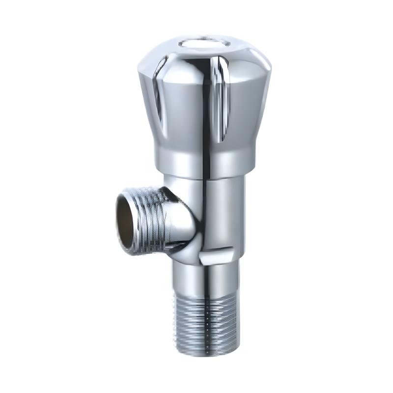
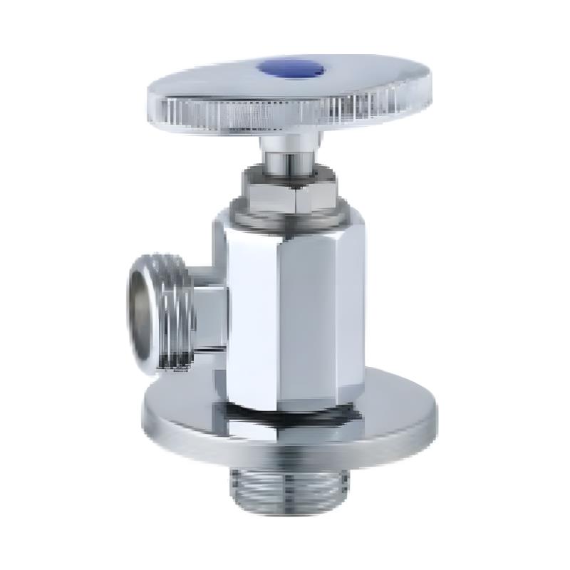
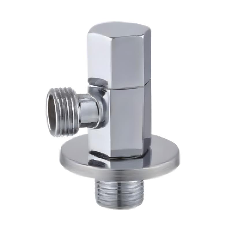
The shape of the valve reflects the geometry of that transition. Inlet and outlet sit at a right angle to each other, which allows the supply line to run horizontally along a wall while the outlet faces the fixture. This arrangement reduces the number of fittings needed and keeps the installation compact in spaces where room is limited.
Understanding how a Heavy Duty Angle Valve works means looking at several layers: the internal mechanism that controls flow, the construction choices that define its duty level, the conditions where it is installed, and the maintenance practices that determine how long it remains serviceable. Each layer connects to the others, and the valve's behavior in a system follows from how they fit together.
What Happens Inside an Angle Valve When the Handle Turns?
The internal operation of an angle valve is straightforward once the parts are separated in the mind.
Water enters through the inlet port and reaches an internal seating area. A stem connects the handle on the outside to a sealing element inside. When the handle turns, the stem moves, and the sealing element either lifts away from its seat or presses down against it. Lifting opens the path for water; pressing closes it.
From the seating area, water changes direction at the angle before leaving through the outlet port. That turn is built into the body of the valve rather than achieved through external elbows or adapters. The result is a shorter flow path and fewer joints where leaks can develop.
A distinction matters here. Some valves serve as simple on‑off devices, either fully open or fully closed. Others allow partial opening, which regulates flow rate rather than simply stopping or starting it. The internal design determines which behavior is possible. A valve intended for isolation may not respond well to being left partly open, while one designed for regulation can hold an intermediate position without undue wear.
What Does the Heavy Duty Designation Actually Reflect?
The term heavy duty describes construction rather than a specific rating. It indicates that the valve is built to handle conditions beyond what a standard unit would tolerate comfortably.
Several factors contribute to that difference:
- Body material and wall thickness suited to sustained pressure rather than occasional use
- Stem and seating components designed for repeated open‑and‑close cycles without losing their sealing ability
- Connection points — threaded, compression, or otherwise — that hold firm under load and vibration
- Handle construction that resists deformation when force is applied
- Tolerance for water conditions that may include minor sediment or temperature variation
A standard valve can serve well in low‑demand situations where it is operated infrequently and access for replacement is easy. Heavier construction becomes relevant when the valve faces regular operation, higher pressure, or a location where servicing is difficult. The cost difference reflects the additional material and machining involved, not a difference in how the valve functions at a basic level.
Duty level also relates to access. A valve buried behind a wall panel or positioned in a cramped mechanical space is harder to reach when problems arise. Choosing heavier construction in those locations reduces the chance of needing to open the wall again.
How Does Water Move Through the Valve Body?
Flow through an angle valve follows a path shaped by the internal geometry.
Water arrives at the inlet under system pressure. When the valve is open, it passes the seating area and turns toward the outlet. The turn introduces some turbulence, and turbulence contributes to pressure loss across the valve. A body with a smoother internal transition reduces that loss, though the effect is modest in most supply applications.
Partial opening changes the picture. When the sealing element sits partway between open and closed, the flow path narrows. This reduces the volume of water passing through and can lower pressure downstream. The valve is not a pressure regulator, but it does influence flow rate at the fixture.
Noise is another consideration tied to internal flow. Higher velocity through a narrow opening produces more sound, and that sound travels through the pipes. A valve operated near its full‑open position tends to run quieter than one left at a small opening. This is one reason isolation valves are typically kept fully open or fully closed rather than used as volume controls.
The materials in contact with water also affect long‑term behavior. Smooth internal surfaces resist mineral buildup, while rougher surfaces give deposits a place to accumulate. Over time, buildup narrows the flow path and can interfere with the sealing element's ability to close completely.
Where Are These Valves Installed and How Do They Connect?
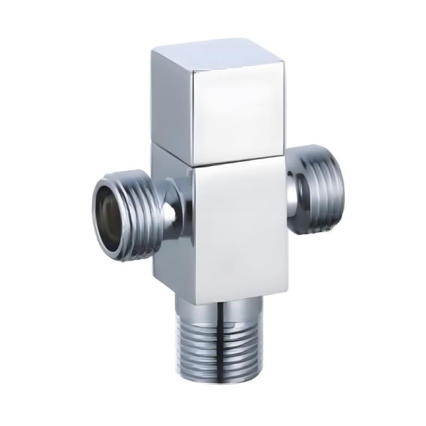
Angle valves appear wherever a supply line needs to meet a fixture or appliance, and the settings vary widely.
- Under‑sink connections feeding faucets, where the valve provides a local shutoff point
- Branch lines supplying appliances such as water heaters, washing machines, or filtration units
- Toilet and bidet supply points, where access is often tight and a compact fitting helps
- Commercial and industrial settings, where equipment connections may see more frequent operation
- Exposed versus wall‑mounted configurations, depending on how the supply line is routed
Connection methods follow from the installation type. Threaded connections are common where the valve can be turned onto a fitting. Compression fittings grip the pipe without threading. Push‑fit options allow connection without tools, though they suit certain pipe materials and conditions rather than all of them.
Orientation affects both operation and maintenance. A handle that faces an open area is easier to turn than one pressed against a cabinet wall. An outlet that points toward the fixture simplifies the final connection and reduces strain on the tubing. These details seem minor at installation but matter when the valve needs to be operated or serviced later.
| Material | Typical Connection | Common Setting | Consideration |
|---|---|---|---|
| Brass | Threaded or compression | Under‑sink, appliance supply | Resists corrosion in many water conditions |
| Stainless steel | Threaded or compression | Commercial, exposed lines | Suited to demanding environments |
| Plated finish over base metal | Varies by base | Residential fixtures | Finish protects appearance, not structure |
| Seal materials (rubber, silicone, PTFE) | Internal component | All settings | Contact water directly, affects sealing life |
| Handle and stem materials | External and internal | All settings | Influence grip, wear, temperature response |
Which Materials Suit Different Water Conditions?
Material choice often gets treated as a matter of preference. In practice, it follows from what the water carries and where the valve sits.
Brass remains common in supply systems because it machines well, holds threads cleanly, and resists corrosion across a range of water conditions. It handles the minerals and slight acidity found in many municipal supplies without developing problems quickly. In water with higher chloride content, brass can show stress corrosion over time, which is where other options enter the picture.
Stainless steel appears where durability carries more weight — exposed lines, commercial settings, or locations where the valve is expected to remain in service without attention. It resists corrosion across a wider range of water chemistry than brass, though it costs more and can be harder to machine into the tight tolerances some valve bodies require.
Plated finishes sit on top of a base metal. Chrome and nickel plating protect appearance and add a layer against surface corrosion, but they do not change what happens inside the valve. A plated body over a base metal unsuited to the water conditions will still develop problems; the finish simply delays visible signs.
Seal materials contact water directly and wear with use. Rubber seals are common and work across many conditions, though some formulations harden with heat or exposure to certain chemicals. Silicone holds up better at temperature extremes. PTFE seats resist chemical attack and reduce friction at the sealing surface, which matters when a valve is operated frequently.
Handle and stem materials affect how the valve feels in use and how it holds up. Metal handles tolerate force better than plastic ones but transmit heat from hot water lines. Plastic handles stay cooler and cost less, though they can crack under heavy tightening. The stem material determines how the sealing element moves and how well it resists wear from repeated turning.
Water chemistry, temperature, and operating frequency together point toward the material that fits a given installation. There is no single answer that covers every case.
What Goes Wrong During Operation and Why?
Problems with angle valves tend to develop gradually rather than appearing without warning. Recognizing the early signs makes a difference in how much service life a valve delivers.
Over‑tightening is a common cause of trouble. Once a valve reaches its closed position, additional force does not improve sealing — it compresses the seat and strains the stem. Repeated over‑tightening deforms the sealing element, and the valve begins to drip even when fully closed.
Mineral buildup accumulates on internal surfaces over time, particularly in areas with hard water. Deposits narrow the flow path and can prevent the sealing element from seating properly. A valve that becomes stiff to turn or produces reduced flow may be showing the early stages of buildup.
Leaks appear at different points depending on the cause. A drip from the stem or bonnet area suggests the packing or stem seal has worn. A leak at a connection point points to a fitting that has loosened or a seal that has degraded. Water appearing around the outlet when the valve is closed indicates the seat is no longer sealing properly.
Stiffness in the handle develops when the stem or seating area accumulates deposits or when the valve has not been operated for a long period. A valve left untouched for an extended time can seize, which turns a simple shutoff into a difficult repair.
Shutoff practices before working on downstream components matter as well. Closing the valve fully and confirming that flow has stopped prevents water from reaching the work area. In systems where multiple valves serve the same line, identifying which one isolates the section is part of the preparation.
How Is Service Life Extended Through Maintenance?
Maintenance for angle valves is modest, but skipping it shortens the interval before replacement.
- Operate the valve periodically — turning it through a full cycle every so often keeps the stem and seat from seizing
- Clean or replace seating components when the valve no longer stops flow completely
- Check access before problems arise, so that servicing does not require opening walls or moving fixtures
- Replace rather than repair when the body itself shows corrosion or damage, since internal repairs do not address structural decline
- Match service intervals to water quality, since hard or mineral‑heavy water accelerates deposit formation
- Keep records for valves in critical or hard‑to‑reach locations, so that age and service history are known
Periodic operation deserves emphasis. A valve that is never turned tends to seize in place, and the force required to free it can damage the stem or seat. Running it through a full cycle during routine maintenance keeps the internal surfaces moving and reveals stiffness before it becomes a problem.
Access planning is easier at installation than later. A valve positioned with room to reach the handle and loosen connections takes less effort to service than one wedged behind a fixture. Where access is limited by design, choosing heavier construction reduces the frequency of service calls.
Replacement decisions follow from the condition of the body rather than the age alone. A valve with a worn seat but sound body can sometimes be serviced. One with corrosion on the body or damaged threads is better replaced, since the structural issues affect the connection rather than just the sealing surface.
How Do Placement and Duty Shape Function?
The angle configuration solves a specific problem. It allows a supply line to meet a fixture without extra fittings, in a space that is often tight. That geometry is the reason the valve exists in its current form, and it shapes how water moves through the body.
Duty level addresses a different concern. Construction suited to sustained pressure and repeated operation extends service life in conditions where a standard unit would need attention sooner. The difference shows up in material thickness, stem design, and connection quality rather than in how the valve opens and closes.
A Heavy Duty Angle Valve works as part of a system rather than on its own. Its performance depends on the water it carries, the pressure it faces, how often it is operated, and how easily it can be reached for service. Those factors point toward the material, connection type, and construction level that fit a given installation.
The valve is a serviceable component, not a permanent fixture. Treating it that way — operating it periodically, checking for early signs of wear, and planning access before problems develop — keeps it functioning as intended for as long as its construction allows.